Similar to other engineering practices cold-formed steel industry also used both imperial and metric versions of the units for measurements. Imperial units are predominantly used in the North American region and Canada while the Metric units are common in places such as Australia. Often there arises confusion amongst users who use a different unit rather than the units commonly used within their region. This confusion prevails commonly while specifying the steel thickness of cold-formed members. Thickness designations in the cold-formed steel (CFS) industry are critical for ensuring proper material usage and compliance with design standards so that the sections meet the minimum thickness requirement for the design of cold-formed steel framing elements.
In general engineering practice, imperial units use Mils, in (inches) and Gauge to specify thickness while the metric system uses mm (millimetres) to measure and specify thickness.
The Importance of Thickness Designations in Cold-Formed Steel Design
Base metal thickness and Design thickness are two important terms used in the design of cold-formed steel members as per different country codes of practice. Framing standards such as AISI-S240 play an essential role in specifying the thickness designation for various structural components such as floor joists, clip angle etc for design purposes. Different thickness designations are explained below in detail.
Base Metal Thickness (BMT)
Base metal thickness refers to the actual, uncoated thickness of the steel sheet. It excludes any additional material from coatings like galvanization or paint. Engineers rely on this value for structural calculations since coatings do not contribute to the material’s strength. BMT is mainly used in the Australian (AS 4600) and Eurocode (EN 1993 1-3) standards for the design.
Practical Example
A steel sheet with:
- Base Metal Thickness (BMT): 0.95 mm.
- Coating Thickness: 0.05 mm (0.025 mm per side).
- Total Thickness: 1 mm.
In this case, the structural design calculations will use 0.95 mm, ignoring the coating as the coating does not affect the structural design capacities. The image below shows the thickness of the coating on the steel surface.

Source: Bluescope technical bulletin
Design Thickness
Design thickness accounts for both the base metal thickness and tolerances allowed by manufacturing processes. This value is often specified in design codes to facilitate the designer. Design thickness and Base Metal thickness are often specified in the American standards to help designers use the appropriate thickness in their design calculation. The table below shows an example of the same from AISI S240.
 Benefits of providing the design thickness include the following.
- Ensures correct tolerances in designing cold-formed steel structures.
- Provides engineers with a reliable basis for design, accommodating real-world variations and ensuring the members are optimally designed.
Note: The design thickness is always equal to or slightly greater than the base metal thickness, depending on manufacturing tolerances.
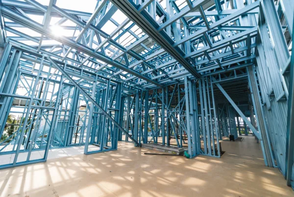
In cold-formed steel construction, tracks play a crucial role in framing as they provide the foundational framework for walls. Tracks are designed in a U-shape and serve as the boundary at the top and bottom of steel stud walls. By defining the start and end of these walls, tracks guide the placement of the studs that fit snugly inside, providing structural integrity.
Key Functions of Tracks:
- Alignment and Stability: Tracks ensure that the steel studs are aligned properly, thus guaranteeing the walls are straight and stable.
- Flexibility in Design: Available in various sizes that match the studs, tracks accommodate different architectural needs without compromising function.
- Ease of Installation: The U-shaped design simplifies the process of securing studs, making the entire construction phase more efficient.
By housing the studs securely, tracks contribute to the overall strength and durability of the steel framing, streamlining the construction process and ensuring a sturdy structure.
Best Practices for Managing Thickness Designations
Understanding the conversion factors between imperial and metric units is crucial in choosing the correct thickness. These play a vital role in the design, procurement and manufacturing stage. Cold-formed steel governing organizations, such as the American Iron and Steel Institute (AISI) and Steel Framing Industry Association (SFIA) publish technical guides and manuals where the conversion factors are readily available. Designers must ensure that these values are followed during the thickness conversion process from one unit to the other. Table showing typical thickness conversions from the SFIA technical guide is shown below.
 The table shows the thickness in Mils, in (inches) and Gauge no for commonly used thicknesses within the cold-formed steel industry. Conversion from inches to millimetres can be done by multiplying inches by a factor of 25.4.
Example calculation
1 in = 25.4 mm, therefore 0.0179 in = 0.45466 mm
For convenience, all values in the table above have been converted into millimetres and are presented below for ready reference.
| Design Thickness (Mils) | Minimum Thickness (mm) | Design Thickness (mm) | Reference Gauge No. |
| 18 | 0.45466 | 0.47752 | 25 |
| 27 | 0.68326 | 0.71882 | 22 |
| 30 | 0.75184 | 0.79248 | 20-Drywall |
| 33 | 0.83566 | 0.87884 | 20-Structural |
| 43 | 1.08712 | 1.14554 | 18 |
| 54 | 1.36652 | 1.43764 | 16 |
| 68 | 1.71958 | 1.81102 | 14 |
| 97 | 2.45364 | 2.58318 | 12 |
| 118 | 2.9972 | 3.15468 | 10 |
How to Identify Cold-Formed Steel Framing Thickness in the Field
When you’re out in the field, assessing the material thickness of cold-formed steel (CFS) framing is crucial. Here’s how you can effectively do it:
1. Check the Manufacturer’s Code
Every piece of steel framing typically comes with a stamped code provided by the manufacturer. This code contains essential information about the stud, including its size and thickness. For example, look for sequences that might signal the gauge and dimensions, which will help you identify the specifications directly.
2. Observe Color Coding
Before they leave the factory, the ends of steel studs and tracks are generally painted a specific color that indicates their thickness. Common color codes include:
- Green: 16-gauge (54 mils)
- Yellow: 18-gauge (43 mils)
These color markings offer a quick visual cue to determine the gauge just by glancing at the ends of the pieces.
3. Use a Micrometer
In situations where labels or color codes are obscured, a micrometer is your next best tool. A C-shaped outside micrometer is ideal for this task, as it can precisely measure the material’s thickness despite its rounded edges. Always take several measurements to ensure accuracy and gain confidence in your assessment.
4. It’s All in the Flange
Though often overlooked, observing the flange can also help identify thickness. The flange width is part of the stamped code, allowing cross-reference with standard sizes to estimate gauge even when direct reading is challenging.
By using these methods, you can reliably determine the material thickness of cold-formed steel framing, ensuring your construction project remains up to code and structurally sound.
How to Measure Cold-Formed Steel Thickness with a Micrometer
When it comes to measuring the thickness of cold-formed steel, a micrometer can be a valuable tool. Here’s how you can use it efficiently:
- Choose the Right Micrometer
Opt for a C-shaped outside micrometer, which is ideal for flat surfaces and provides accurate readings. Unlike inside micrometers, which can struggle with uneven, rounded edges, the outside micrometer fits the requirements perfectly. - Prepare the Surface
Ensure the steel surface is clean and free from debris that could affect the measurement. A smooth and clean surface allows the micrometer to rest accurately against the material. - Taking Measurements
- Position the Micrometer: Open the micrometer enough to fit around the steel piece, then gently close it until it is snug against the material.
- Read the Measurement: Carefully read the scale on the micrometer. Be sure to align your eyes directly with the scale for an accurate reading.
- Confirm the Accuracy
Take multiple readings at different locations across the steel surface. This helps verify the consistency of your measurements, ensuring that you have accurately gauged the material’s thickness.
By following these steps, you can rely on a micrometer to provide precise measurements of cold-formed steel, thereby supporting your project’s specifications and requirements.
Limitations of Online Metal Thickness Gauges for Cold-Formed Steel
When shopping online for metal thickness gauges, it’s important to understand their limitations, especially when dealing with cold-formed structural steel. Here’s what you need to know:
- Designed for Sheet Metal: Most gauges found online are crafted mainly for measuring sheet metal. As such, they may not provide the most accurate readings for cold-formed steel, which is notably different in density and durability.
- Precision Issues: These gauges might only offer a rough estimate, as they aren’t specifically engineered for the unique properties of cold-formed steel. This can lead to less precise thickness judgments.
- Ideal Measurement Points: To enhance accuracy, it’s recommended to measure at stud knockouts rather than rolled edges. The latter can often distort readings due to their shape and additional processing.
In essence, online gauges can guide you toward an educated guess, but they may not fulfill the stringent precision requirements for detailed structural applications.
Understanding the color markings on cold-formed steel is crucial for identifying thickness variations, which can affect both structural integrity and application. Each color is a coded indicator of the steel’s gauge and thickness.
Steel Thickness Color Code
Before these steel components leave the factory, the ends of steel studs and tracks are painted with specific colors. Let’s break down these color indicators for clarity:
- Blue: Represents a thickness of 118 mils, correlating to 10-gauge steel.
- Red: Indicates 97 mils, which corresponds to 12-gauge steel.
- Orange: Designates a 68-mil thickness, suitable for 14-gauge steel.
- Green: Marks a thickness of 54 mils, aligning with 16-gauge steel.
- Yellow: Stands for 43 mils, matching 18-gauge steel.
- White: Denotes 33 mils and is often used for 20-gauge steel.
- Pink: Also indicates 30 mils, albeit as an interior-use only variation of 20-gauge steel.
- Black: Signals a 27-mil thickness, related to 22-gauge steel.
Why Use Color Markings?
The use of color markings is a streamlined way to quickly identify the steel’s thickness without the need for measurement. This system ensures efficiency on construction sites and during quality checks in manufacturing. By relying on these markings, professionals can easily select the appropriate steel type for different structural applications.
Identifying Steel Thickness with Color Markings
When it comes to construction, distinguishing between different thicknesses of steel studs and tracks is crucial. This is where color markings become incredibly useful. Before these steel components leave the factory, their ends are painted with specific colors. Each color represents a different thickness, making it easy for builders to select the right material without measuring each piece manually.
Why Color Markings Matter
Color markings provide a straightforward visual guide. This not only speeds up the construction process but also helps reduce the likelihood of errors. For instance, a quick glance at the color can instantly tell workers the gauge of the steel they are handling.
Color Codes and Their Meanings
Here is a breakdown of common color codes:
- Blue: Indicates a thickness of 118 mils, which corresponds to a 10-gauge steel.
- Red: Represents 97 mils, or 12-gauge steel.
- Orange: Signifies a 68 mils thickness, meaning 14-gauge steel.
- Green: Used for 54 mils, denoting 16-gauge steel.
- Yellow: Corresponds to 43 mils, which is 18-gauge steel.
- White: Signals a thinner steel at 33 mils, equating to 20-gauge.
- Pink: Also for 30 mils, reflecting interior-use only 20-gauge steel.
- Black: Marks the thinnest at 27 mils, equivalent to 22-gauge steel.
By clearly indicating the thickness, these color markings assist in ensuring that the correct materials are used, which is essential for structural integrity and safety. This system not only streamlines the construction process but also prevents costly mistakes, making it an indispensable part of modern building practices.
Estimating Metal Thickness with Everyday Items
When precise measuring tools are out of reach, common household items can effectively help gauge metal thickness. Understanding these everyday items will allow you to make quick estimations without specialized equipment.
Coins: Your Pocket-Sized Gauge
Coins are a reliable stand-in for metal thickness measurements:
- Quarter: This familiar coin is approximately 0.069 inches thick. In terms of metal gauges, it aligns closely with 14-gauge.
- Dime: Slightly thinner, a dime measures about 0.053 inches thick, making it a good reference for 16-gauge metal.
U.S. Dollar Bill: A Flexible Standard
Even paper currency can assist in estimating metal thickness:
- Dollar Bill: At a mere 0.0043 inches thick, a single bill might seem too thin. However, with a few quick folds, you can stack it up to around 0.043 inches, which corresponds closely with 18-gauge metal.
By leveraging these common items, you can make informed approximations about metal thickness without the hassle of hunting down specialized tools.
What to Do When Cold-Formed Steel Lacks Identifying Marks
When you’re dealing with cold-formed steel that has no visible identifying marks, precise measurements become crucial. Here’s a step-by-step guide to ensure you’re assessing the material accurately:
- Select the Right Tool: Begin by choosing a C-shaped outside micrometer. This tool is ideal for measuring the thickness of the material since it can easily handle the flat surfaces of steel without much hassle.
- Avoid Common Pitfalls: Be cautious with inside micrometers for these measurements. They can be challenging to use on materials with rounded, sheared edges, such as cold-formed steel, which makes accurate readings more difficult.
- Multiple Measurements for Accuracy: To ensure reliability, take several measurements at different points on the steel. This practice helps confirm that your thickness determination is consistent and precise.
By following this approach, you can confidently assess the thickness of the steel even in the absence of identifying marks.
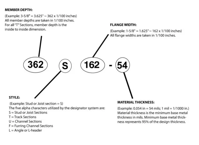
Naming Conventions and Implications in Design and Construction
Standardizing the correct naming conventions to represent thickness is important for communication between stakeholders within a project. This includes architects who arrive at the room dimensions, engineers who design the structural elements for specified thicknesses, the procurement team for sourcing the correct thickness from the steel supplier, manufacturing professionals who load the correct thickness of coil into the roll formers and finally the installation team erecting the fabricated structural elements with correct thickness. Therefore, the designation of the members must be in such a way that all the stakeholders understand the importance of the naming conventions and their significance during the entire construction process.
Standards such as AISI S202 and 220 state that “structural members and non-structural members shall use a four-part product designator that identifies the size (both web depth and flange width), style and thickness. A typical example is shown below, representing the material thickness of a C-section.

By choosing a standardized naming convention across the industry all stakeholders are well informed and the margin of error in choosing the wrong thickness of steel reduces significantly, thereby increasing efficiency in design and construction.
Understanding the Importance of Codes on Metal Studs
The codes printed on metal studs serve as vital identifiers that convey several key attributes of the product. Each element of the code provides specific information that helps in the selection and application of the stud in construction projects.
- Size Identification: The first portion of the code typically indicates the width of the stud, which is a crucial factor for determining its suitability for various wall framing applications. For example, a 6-inch designation confirms the actual size of the stud.
- Gauge or Thickness: The gauge is another critical component of the code, representing the thickness of the metal in mils. Knowing whether a stud is 16-gauge or another specification helps contractors select the right strength and durability for their needs.
- Flange Dimensions: The code often includes measurements of the stud’s flange, generally described in terms of inches. This is important for ensuring the stud fits properly within the structural framework and meets design requirements.
- Steel Strength: A specification such as “50 ksi” within the code indicates the steel strength, measured in kilopounds per square inch. This information is essential for assessing the load-bearing capability of the stud.
However, it’s worth noting that sometimes these labels can become difficult to read, either due to being cut off or misaligned. Despite this challenge, the printed code remains a crucial factor in maintaining construction quality and integrity.
Understanding the Role of Straps in Cold-Formed Steel Construction
In the realm of cold-formed steel construction, straps play a crucial role in ensuring structural stability. These thin sheets of steel, which range from 2 inches to 12 inches in width, are primarily employed to handle tension loads effectively.
Key Applications of Straps
- Wall Bracing: Straps are integral components in wall bracing systems. They enhance the strength and rigidity of the walls by holding them firmly in place, minimizing movement under load.
- Shear Walls: When it comes to shear walls, straps are indispensable. They provide essential support against lateral forces, such as those caused by wind or seismic activity, thereby preventing structural failure.
Why Use Straps?
- Versatility: Available in various widths, straps can be customized to meet specific construction needs.
- Durability: Made from high-quality steel, they are designed to withstand significant tension, ensuring the longevity of the structure.
- Ease of Installation: Straps are relatively easy to install, making them a practical choice for builders aiming for efficiency and reliability.
In summary, straps are a vital component in cold-formed steel construction, ensuring that structures not only stand firm but also endure the tests of time and nature.
How Are L-Headers Used in Cold-Formed Steel Framing?
L-headers are an essential component in cold-formed steel framing, providing crucial support for structural elements. Primarily, they are used to distribute loads above openings such as windows and doors. This enhances the overall strength and stability of the framework.
Key Uses of L-Headers:
- Supporting Openings:
- L-headers act as load-bearing elements that redistribute stress around openings. This is vital in maintaining the integrity of the structure, especially where walls are interrupted by such gaps.
- Custom Adaptability:
- Available in various dimensions, L-headers can be custom bent to suit specific project needs. This flexibility allows for precise engineering tailored to architectural demands without compromising stability.
- Efficiency in Construction:
- Their design simplifies installation, reducing the need for additional support materials. This efficiency not only speeds up construction but also decreases material costs.
By incorporating L-headers, construction projects benefit from improved load distribution and enhanced structural resilience, ensuring buildings can bear dynamic forces effectively.
Understanding the Role of Furring Channels in Cold-Formed Steel Construction
A furring channel is a versatile component in cold-formed steel (CFS) construction, often referred to as a “hat channel” due to its distinctive shape. Here’s why it’s crucial in the building process:
- Creating Space and Alignment: Furring channels are primarily used to create a space or gap between the framing and the finish materials. This helps in aligning uneven surfaces, ensuring a smooth and level finish on walls or ceilings.
- Moisture Management: By providing a gap, these channels help with moisture control. This space allows for air circulation, which can prevent the buildup of moisture that could lead to mold or deterioration over time.
- Thermal and Acoustic Insulation: These channels contribute to better insulation by acting as a thermal break. This reduces the transfer of heat, improving energy efficiency. Additionally, they help in enhancing sound insulation by adding an extra layer for noise reduction.
- Ease of Installation: Furring channels simplify the installation of drywall or other sheathing materials. They provide a uniform surface, making the attachment of finishing materials easier and faster.
In sum, furring channels play a critical part in CFS construction, enhancing structural integrity while improving insulation and facilitating a polished final appearance.
Scottsdale’s Approach to Steel Thickness
Scottsdale’s bespoke cold-formed steel engineering software packages such as ScotSteel and ScotStruct offer a great range of options for our customers and end users to choose between different units at any stage of the design process. The application and project settings within the software allow the user to design using the Imperial OR Metric system giving the much-needed flexibility on international and local projects. Screenshot below shows the various options supported by ScotSteel in both imperial and metric units.
 In addition, ScotSteel and the entire suite of software packages support the four-part product designator for all sections supported by Scottsdale and Knudson series of roll formers. Screenshot below shows a clear description of the section and corresponding thickness with BMT specified along with the grade of steel within ScotSteel.
 Scottsdale also has ICC certifications for all the sections and the respective reports can be downloaded from the attached link – Download ICC certifications.
How is a U-channel utilized in cold-formed steel framing?
A U-channel, often known as a cold-rolled channel (CRC), plays a pivotal role in cold-formed steel framing systems. These channels are typically fashioned in a smaller U-shape, making them versatile components in construction projects.
Key Uses of U-Channels in Steel Framing:
- Bracing: U-channels are threaded through the pre-punched holes in studs, providing essential bracing. This stabilizes the entire structure, ensuring robustness and reliability under various loads.
- Ceiling Support: They are frequently employed to support ceiling frameworks. When paired with hanger wires, U-channels can efficiently hold ceiling tiles and other materials, maintaining smooth and even surfaces.
- Size and Versatility: The most common sizes for U-channels are 3/4”, 1-1/2”, and 2”. These dimensions allow them to fit into various structural components seamlessly, making them adaptable for different construction needs.
U-channels are integral to steel framing systems by providing structural stability and facilitating the installation of various building elements. Their adaptability in size and application underscores their importance in modern construction techniques.
Understanding the Role of Studs in Cold-Formed Steel Framing
In cold-formed steel framing, studs are essential components known for their unique C-shape design with a lip return. Their primary function is as vertical supports within the wall structure. These elements lend strength and stability to the overall framework, ensuring that walls are both robust and secure.
Key Features and Variability
- Size Variety: Common widths for these studs are 3 5/8 inches and 6 inches, but they can be found in sizes reaching up to 16 inches. This range allows for flexibility in design and load requirements.
- Structural Integrity: By integrating these steel studs, builders can create walls that are not only straight and plumb but also able to withstand significant loads and stresses.
Benefits of Using Steel Studs in Construction
- Durability: Steel is resistant to rot, mold, and pests, offering a long-lasting solution for building projects.
- Fire Resistance: Cold-formed steel framing provides enhanced fire safety compared to traditional wood framing.
- Design Flexibility: With varied sizes and easy installation, steel studs adapt to both residential and commercial construction needs.
In summary, the function of a stud in cold-formed steel framing is pivotal to constructing reliable, durable, and efficient wall structures. Its versatility and strength make it a favored choice among builders seeking quality and longevity in their projects.
Conclusion: Mastering Thickness Designations
In the cold-formed steel industry, understanding the nuances of thickness designations is essential for successful project execution. Whether you’re working with mils, millimetres, gauge, or inches, knowing how to interpret and apply these measurements ensures accurate material selection, design and fabrication. Moreover, distinguishing between base metal and design thickness is critical for accurate structural design.
By integrating best practices and following the standards, industry professionals can navigate these complexities confidently, paving the way for efficient, sustainable, and safe construction practices.