If you supply steel studs and track to drywall and curtainwall framing contractors, your margins live and die at the intersection of two unforgiving variables: how light a gauge you can ship, and how much linear footage you can produce per hour. Specifiers want thinner steel. Installers want studs that handle well and bite screws cleanly. Engineers want sections that pencil out under AISI S100 effective-width calculations. And every minute the line is stopped for a profile changeover is a minute you are paying for steel, labor, and floor space without producing a single billable foot.
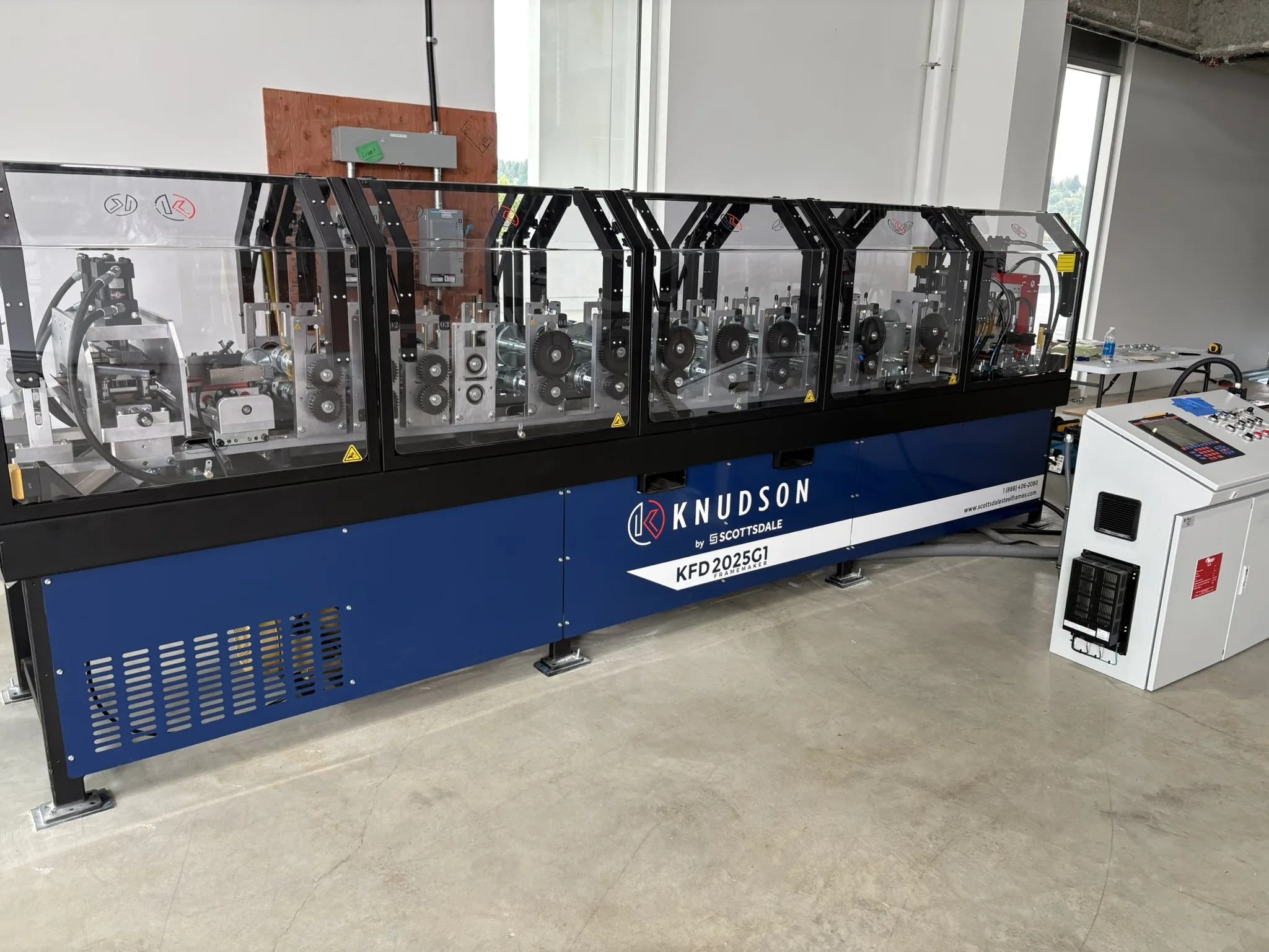
The Knudson by Scottsdale KFD Framemaker 2025, manufactured by Scottsdale Construction Systems, was engineered specifically to win on all three counts. This article walks through the production specifications and — more importantly — the section geometry the machine produces, with a focus on why every stiffening rib, knurled face, and inward-bent lip it forms into the steel translates directly into structural performance, code compliance, and bottom-line value for your operation.
KFD Framemaker 2025: Production Roll Forming Engineered for 20–25 Gauge Drywall and Curtainwall Framing
What Does the KFD Framemaker 2025 Produce
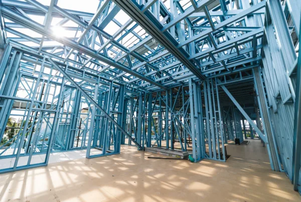
The KFD platform is purpose-built for non-structural and non-load-bearing framing — the high-volume drywall, partition, ceiling, shaft-wall, and curtainwall back-up applications that dominate commercial construction interior packages. Per Scottsdale’s published specifications, the machine forms:
| Parameter | Specification |
| Stud web depths (A) | 1.63″, 2.50″, 3.63″, 4.00″, 6.00″ |
| Stud flange height (B) | 1.25″ |
| Stiffening lip return (C) | 0.20″ |
| Track flange height (Y) | 1.50″ max |
| Inside bend radius (r) | 0.060″ |
| Material thickness (t) | 0.018″ – 0.035″ (25 Ga – 20 Ga) |
| Production speed | Up to 120 ft/min (servo-electric drive) |
| Steel grade compatibility | Up to 65 ksi yield / 75 ksi tensile |
| In-line punching | Hydraulic — service hole, index, anchor hole, deflection track slot |

That last row is worth pausing on. The integrated deflection track slot punches are the feature that makes this machine genuinely curtainwall-ready, not just drywall-ready. Slip-track and head-of-wall connections in exterior curtainwall back-up framing require slotted attachment points that allow vertical movement under thermal and live-load deflection. Forming those slots in-line eliminates a downstream labor step and a major source of dimensional error.
For structural and load-bearing applications in heavier gauges, Scottsdale offers the KFS Framemaker line, which forms 18 Ga to 12 Ga. The KFD and KFS together cover virtually the entire commercial steel framing application gamut.

Why Thin-Gauge Geometry Is the Whole Game
Here is the technical reality that separates serious roll-forming equipment from commodity machines: at 0.018 to 0.035 inches of base metal thickness, section capacity is not controlled by yield strength — it is controlled by local and distortional buckling.
This is not a marketing claim. It is the foundational premise of the North American Specification for the Design of Cold-Formed Steel Structural Members (AISI S100), now maintained as ANSI/SDI AISI S100-2024. The entire Effective Width Method that engineers use to qualify a thin-gauge member exists because flat, slender plate elements in compression buckle out of plane long before the steel reaches its yield stress. Critical buckling stress falls with the square of the width-to-thickness ratio (w/t). A 6-inch web at 0.018 inches has a w/t of approximately 333. Without geometric intervention, a stud like that would lose the majority of its theoretical capacity to local buckling.
Geometric intervention is exactly what the KFD Framemaker 2025 builds into every member. Three features in particular — visible on every stud the machine produces — convert a structurally marginal flat shape into a code-qualifying, contractor-friendly section.
Feature 1: Stiffened Corners at the Flange-Web Intersection
Look at the profile drawing for the stud and you will see small longitudinal reinforcement marks rolled into the steel right where each flange meets the web. These are intermediate stiffeners — small ribs or dimples formed during one of the multi-stage forming passes the steel travels through.
The flange-web junction is the most demanding region of any C-section. It is where shear flow peaks, where web vertical compression meets flange horizontal bending, and where any tendency toward distortional buckling — the failure mode in which the flange-and-lip assembly rotates as a unit about the corner — originates. Distortional buckling is often the governing limit state for slender drywall studs, and it is notoriously sensitive to the rotational stiffness of exactly this corner.
A flat, unmodified corner has very little stiffness along the length of the member. Roll a small longitudinal rib into the steel at that location and the local moment of inertia jumps by an order of magnitude. The corner now resists rotation. Distortional buckling wavelengths get pushed longer, raising the buckling stress. The web’s effective width at its compression edge increases because the edge support is now stiffer.
What was a slender unstiffened plate edge becomes an edge backed by a small longitudinal tube. That conversion adds meaningful capacity — at zero added steel, because the stiffener is formed from existing material during the rolling pass. This is the kind of “free” performance gain that only comes from purpose-built tooling and a properly sequenced roll-forming line.
Feature 2: Knurled Flanges
The diagonal cross-hatching pattern shown on the flanges represents knurling — a fine, repeating array of shallow indentations rolled into the flange surface during forming. Knurling is sometimes mistaken for cosmetic finish or a screw-grip enhancement. It is both of those things, but in thin-gauge framing the structural role is the most important one.
A flange in bending carries compression on one side of the neutral axis. The compression side wants to buckle locally — to ripple into a series of out-of-plane waves whose wavelength depends on the plate’s flexural stiffness. A flat flange has only its base flexural stiffness, D = E·t³ / 12(1-ν²), which scales with the cube of thickness. At t = 0.018 inches, that flexural stiffness is roughly one-eighth of what it is at 0.035 inches. Thin flanges buckle very, very easily.
Knurling pushes back on this in three ways:
The first is work-hardening. Each knurl indentation cold-works the steel beneath it, locally raising the yield strength of the material the flange is made of. The flange no longer behaves as a pristine plate at base yield; it behaves as a slightly stronger plate everywhere the knurls touch it.
The second is buckling-mode disruption. Local buckling depends on a smooth, continuous plate developing a regular sinusoidal deflection pattern. A flange surface covered with thousands of small geometric perturbations cannot easily settle into the shape that buckling requires. The plate becomes harder to buckle because the buckling mode itself is geometrically interrupted.
The third is screw retention — and this is where the technical-sales argument becomes a contractor-economics argument. Drywall screws driven into 25-gauge steel without knurling tend to spin, strip, or cam-out, especially with cordless impact drivers running at modern torque settings. The knurled surface gives the screw tip something to engage on contact. Drive failures drop. Pull-out resistance becomes more consistent. For an installer hanging hundreds of screws an hour, the savings in labor and rework are immediate. Stud and track suppliers whose product reliably accepts a screw on the first try generate repeat orders that flat-flange producers do not.
The KFD Framemaker 2025 introduces knurling at a dedicated forming station, ensuring uniform pattern depth and density across every flange, every stud, every shift.
Feature 3: Inward-Bent Stiffening Lips
The stiffening lip — the small return at the open edge of each flange, dimensioned at 0.20 inches on the KFD profile — is the single most important geometric feature on any thin-gauge C-stud. Without it, the flange is what AISI S100 classifies as an unstiffened element: a plate with one supported edge (at the web) and one free edge (at the open side of the C). Unstiffened elements have very limited effective width once they buckle. Add a properly proportioned lip and the flange becomes a stiffened element with both edges restrained, and its effective width — therefore its load capacity — increases dramatically.
But notice something specific about the geometry. The lip is bent slightly inward, not at a perfect 90 degrees, and not bent outward. This subtle angle is deliberate, and it is critical at thin gauges.
A lip bent at exactly 90 degrees becomes its own slender element with its own free edge, susceptible to its own form of local buckling. If the lip itself buckles, it can no longer restrain the flange edge, and the entire stiffening benefit is lost. AISI S100 explicitly imposes lip-to-flange ratio limits because an over-long or under-supported lip will fail before it can do its job. The updated AISI S100-16 commentary addresses this directly through its treatment of edge stiffeners.
By bending the lip slightly inward — typically somewhere between 80 and 85 degrees from the flange — the KFD Framemaker 2025 achieves several outcomes simultaneously. The lip is geometrically prevented from rotating outward under load, because doing so would require it to first un-bend through the flange. The lip-flange junction acts as a partially closed corner, increasing the torsional stiffness of the entire flange-lip assembly. Distortional buckling resistance improves markedly, because the inward angle places the lip’s mass closer to the web, shortening the rotational lever arm.
Two practical, non-structural benefits also come along for the ride. Inward lips keep the overall profile compact, which matters when studs are nested for shipping or stacked into a track on the deck. And — critically for drywall practice — an inward-facing lip cannot snag drywall paper, gypsum edges, or vapor barriers during installation. An outward-facing lip on a 25-gauge stud is essentially a row of small knife edges. An inward-facing lip is a smooth, rounded back.
Why Roll Forming Is the Only Path to This Geometry
It is worth being explicit: the geometry described above — corner stiffeners, knurled flanges, and precisely-angled inward lips — cannot be achieved by press braking, stamping, or any single-station forming process. These features develop progressively as the steel strip travels through a carefully sequenced series of forming passes, each making a small, controlled change to the cross-section, each timed to avoid material thinning, springback misalignment, or surface marring.
The KFD Framemaker 2025 (G2 configuration) executes this through a 9-roller forming cage, with auto-shutoff safety panels, an integrated batch printer, and software-controlled gauge-change automation. The full process — coil decoiling, infeed centering, multi-station forming, in-line punching, hydraulic shear, and discharge — is documented in Scottsdale’s overview of the roll forming process.

The Production Economics
Geometric performance matters only if you can produce members at a competitive volume and cost. Here, the KFD Framemaker 2025 delivers on several production levers simultaneously:
Throughput – Up to 120 feet per minute on the servo-electric drive. For a single-shift operation running 6 productive hours a day, that’s roughly 43,000 linear feet per day of stud or track at full speed.
Material flexibility – A single coil grade running up to 65 ksi yield / 75 ksi tensile covers the vast majority of drywall and curtainwall specifications. Multi-profile capability across five web depths means one machine can run the entire interior partition slate without retooling for a new product line.
Software-driven changeover – The KFD integrates with Vertex BD, Graitec Strucsoft MWF, ScotRF, and ScotSteel — meaning batch lists, cut lengths, and punch patterns flow from design software directly to the machine controller. No manual transcription, no staging delays.
In-line punching – Service holes, index marks, anchor holes, and deflection track slots are formed in the same pass as the section itself. Downstream secondary operations are eliminated.
Compliance – Members produced on the KFD platform are designed to comply with the cold-formed steel specifications recognized by BuildSteel.org and the Steel Deck Institute, the standards bodies that maintain the design framework engineers reference for project specification.
A more comprehensive look at the platform-level economics — including software, financing, and complementary equipment — is available on Scottsdale’s benefits page and in the broader Scottsdale ecosystem overview.
Who Should Be Specifying This Machine
The KFD Framemaker 2025 is the right call for:
#1 Stud and track suppliers serving commercial drywall, partition, and ceiling markets who need full-range coverage of the 1-5/8 through 6-inch web sizes at 20–25 gauge with structurally optimized geometry.
#2 Curtainwall framing fabricators who require in-line deflection track slot punching and need a machine capable of producing both the lipped stud and the unlipped track on the same platform.
#3 Panelized and modular construction operations running off-site fabrication of partition wall assemblies, where software-to-CNC integration determines whether the line meets its production schedule.
#4 Steel framing manufacturers expanding their product slate who already operate a Scotpanel or KFS Framemaker for structural production and want to add a non-structural line without disrupting existing workflow.

Specify, Quote, and Demo
For full technical documentation, sample profiles, production capacity modeling, and equipment financing options on the KFD Framemaker 2025, contact Scottsdale Construction Systems directly:
- Phone: +1 (888) 406-2080
- Email: sales@scottsdalesteelframes.com
- Web: scottsdalesteelframes.com
- Product page: Knudson by Scottsdale KFD Framemaker
- Full machine catalog: Scottsdale roll-forming equipment
A free demo, profile-specific capacity analysis, and software integration walkthrough are available on request.