Modern builders continue to search for better ways to improve energy efficiency without sacrificing durability or construction speed. In today’s market, thermal performance has become one of the most important design considerations for projects using cold-formed steel. Designers must also reduce thermal bridging, improve every thermal CFS wall strategy, optimize roll forming production, strengthen steel framing practices, and refine CFS wall assemblies to meet stricter energy expectations.

What is Thermal Bridging?
Thermal bridging occurs when heat transfers through conductive materials that pass through insulation layers within a wall assembly. In building envelopes, framing members can create direct pathways for heat movement between the interior and exterior environments. In cold-formed steel construction, thermal bridging is an important design consideration because steel conducts heat approximately 300 to 400 times faster than wood.
Research and field testing have shown that thermal bridging can influence the effective insulation value of a wall assembly compared to its center-of-cavity insulation rating. R-value measures a material’s resistance to heat flow. Higher R-values indicate greater insulation performance and improved thermal efficiency. “R-19 cavity insulation” refers to insulation installed within the wall cavity between framing members that provides a nominal thermal resistance value of R-19. A wall with R-19 cavity insulation may perform closer to R-11 to R-13 once the impact of steel studs is included in the overall assembly calculation. This is why many modern CFS wall assemblies incorporate continuous exterior insulation, air barriers, and advanced detailing methods to support improved thermal performance in steel framing systems.
Steel framing systems are designed with thermal conductivity in mind, which is why modern building envelopes often incorporate continuous exterior insulation and carefully engineered CFS wall assemblies. Because steel transfers heat efficiently, many thermal CFS wall designs use layered insulation strategies to support overall thermal performance across the assembly. Advanced roll forming technology also improves framing accuracy and installation consistency, helping insulation systems align more effectively throughout the building envelope.
Reducing Thermal Bridging in Exterior Walls
One of the biggest challenges in cold-formed steel construction is controlling thermal bridging through structural members. Because steel transfers heat much faster than wood, thermal bridging can dramatically reduce insulation efficiency when wall systems are not designed correctly. Builders working with steel framing often rely on continuous exterior insulation to interrupt thermal bridging and protect interior spaces from heat loss.
Another important factor is coordination between insulation placement and roll forming accuracy. Precision manufacturing allows installers to align framing systems properly, which helps reduce gaps and inconsistencies inside CFS wall assemblies. When engineers focus on both detailing and installation quality, overall thermal performance improves significantly.

Designing a Better CFS Wall System for Thermal Bridging
A high-quality thermal CFS wall design begins with understanding climate conditions, insulation ratios, and moisture management. In many projects, cold-formed steel systems perform exceptionally well when paired with exterior rigid insulation and carefully sealed air barriers. This combination limits thermal bridging while helping contractors achieve long-term thermal performance goals.
Manufacturers involved in roll forming can further support efficiency by producing framing profiles with consistent tolerances. Accurate components reduce installation errors and help steel framing crews maintain continuous insulation layers. Many advanced CFS wall assemblies now incorporate exterior insulation, mineral wool, or spray foam systems to improve durability, indoor comfort, and thermal performance for demanding projects.
Building Better CFS Wall Assemblies in Modern Construction
Today’s CFS wall assemblies are designed to balance structure, insulation, and moisture control in a single coordinated system. Many CFS wall assemblies now include rigid exterior insulation, air barriers, and rainscreen systems that work together to improve thermal performance in demanding climates.
Builders using cold-formed steel also understand the importance of minimizing thermal bridging at headers, tracks, and connection points. Proper detailing around windows, doors, and roof transitions helps every thermal CFS wall maintain efficiency throughout the life of the structure. Accurate fabrication processes further improve CFS wall assemblies by ensuring framing systems align correctly with insulation and cladding systems.

Watch a quick video, “Interesting Illustration of a Scottsdale LGS Assembly“, highlighting how the steel framing components integrate with the vapor barrier system to create a precise and efficient building envelope assembly.
Below, we highlight key concepts commonly used when designing CFS wall systems across different climate zones and performance targets.
Vapor Retarder Classification Summary
| Vapor Retarder Class | Permeance Range | Common Examples | Typical Applications |
| Class I | ≤0.1 perms | Polyethylene sheet, foil-faced insulation | Cold climate projects and high vapor control applications |
| Class II | >0.1 and ≤1.0 perms | Kraft-faced insulation, vapor retarder paints | Mixed climate wall systems |
| Class III | >1.0 and ≤10 perms | Latex paint, vapor-open interior finishes | Hot and mixed climate assemblies |
Vapor Drive Direction Summary
| Climate Type | Typical Climate Zones | Primary Vapor Drive | Common Design Strategy |
| Heating-Dominated Climates | Zones 5-8 | Interior to exterior | Interior vapor control with exterior insulation |
| Cooling-Dominated Climates | Zones 1-2 | Exterior to interior | Vapor-open interior finishes |
| Mixed Climates | Zones 3-4 | Bidirectional | Balanced permeability and smart vapor retarders |
Thermal CFS Wall Assembly Types
| Assembly # | Wall Assembly Type | Description | Effective R-Value | Typical Performance Range |
| Assembly 1 | Cavity Insulation Only | Batt insulation between steel framing members | R-11 to R-13 | Baseline thermal performance |
| Assembly 2 | Continuous Exterior Insulation | Exterior rigid insulation with furring strips combined with cavity insulation | R-21 to R-28 | Improved thermal performance and insulation continuity |
| Assembly 3 | Split Insulation System | Larger percentage of exterior insulation with furring-supported cladding systems | R-25 to R-35 | Higher-performing thermal CFS wall systems |
| Assembly 4 | Spray Foam Hybrid | Combination of spray foam, batt insulation, and exterior insulation with furring strips | R-30 to R-38 | Enhanced air sealing and thermal control |
| Assembly 5 | Double-Stud Wall | Multi-layer framing and insulation approach with exterior insulation and furring-supported cladding | R-40 to R-50 | High-performance CFS wall assemblies |
Learn more about Furring Channels and Knudson by Scottsdale KSE family of roll forming machines that fabricate these nonstructural sections.


Prescriptive Solutions for Achieving Higher R-Values
| Target Effective R-Value | Option | Example Assembly | Stud Size | Stud Spacing | Exterior Insulation | Interior/Cavity Insulation | Effective R-Value |
| R-20 | Option A | Continuous exterior insulation assembly | 6 in. CFS studs | 24 in. o.c. | 1.5 in. XPS rigid insulation | R-19 cavity insulation | R-21 |
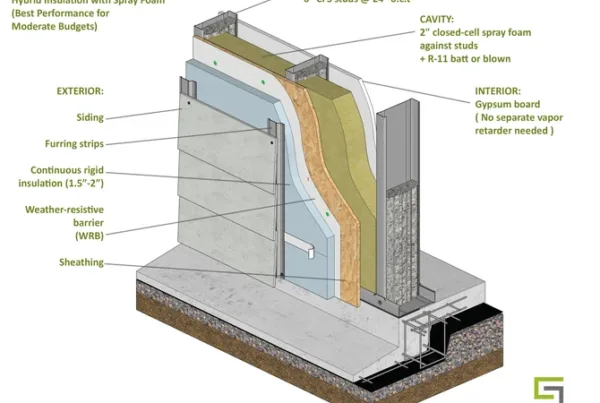
| R-20 | Option B | Moderate exterior insulation with spray foam hybrid | 6 in. CFS studs | 24 in. o.c. | 1 in. rigid insulation | 1.5 in. closed-cell spray foam with R-11 batt insulation | R-22 |
| R-25 | Option A | Heavy exterior insulation assembly | 6 in. CFS studs | 24 in. o.c. | 2.5 in. polyiso insulation | R-19 cavity insulation | R-28 |
| R-25 | Option B | Split insulation system | 4 in. CFS studs | 24 in. o.c. | 3 in. polyiso insulation | R-13 cavity insulation | R-26 |
| R-25 | Option C | Spray foam hybrid assembly | 6 in. CFS studs | 24 in. o.c. | 1.5 in. rigid insulation | 2 in. closed-cell spray foam with R-13 batt insulation | R-27 |
| R-30+ | Option A | Maximum split insulation system | 4 in. CFS studs | 24 in. o.c. | 4 in. polyiso insulation | R-13 cavity insulation | R-32 |
| R-30+ | Option B | Spray foam and heavy exterior insulation assembly | 6 in. CFS studs | 24 in. o.c. | 2 in. rigid insulation | 3 in. closed-cell spray foam with R-11 batt insulation | R-33 |
| R-30+ | Option C | Double-wall insulation system | Double 4 in. CFS stud walls | 24 in. o.c. | 2 in. polyiso insulation | R-30 dense-pack cellulose | R-38 |
| R-40+ | Option A | Deep cavity and heavy exterior insulation assembly | 8 in. CFS studs | 24 in. o.c. | 3 in. rigid insulation | 4 in. closed-cell spray foam with R-15 batt insulation | R-44 |
| R-40+ | Option B | Double-wall high-performance system | Double 4 in. CFS stud walls | 24 in. o.c. | 4 in. polyiso insulation | R-30 dense-pack cellulose | R-48 |
Learn more about the double-wall steel framing system by reviewing “Steel Framing: A Powerful Response to Thermodynamic Challenges”.

Vapor Retarder Selection Guide
| Climate Zone | Climate Type | Recommended Vapor Retarder Approach |
| Zones 1-2 | Hot-Humid / Hot-Dry | Class III or vapor-open interior finishes |
| Zone 3 | Warm-Humid / Warm-Marine | Vapor retarder paint or kraft-faced insulation |
| Zone 4 | Mixed-Humid / Mixed-Marine | Class II or smart vapor retarders |
| Zone 5 | Cool-Humid | Class II vapor retarders or increased exterior insulation |
| Zones 6-7 | Cold / Very Cold | Class I or II vapor retarders with controlled insulation ratios |
| Zone 8 | Subarctic | Class I vapor barriers with advanced moisture control |
Insulation Material Selection Summary
| Insulation Type | Approximate R-Value per Inch | Common Advantages |
| Fiberglass Batt | R-3.2 to R-4.3 | Cost-effective and widely available |
| Mineral Wool | R-3.8 to R-4.3 | Fire resistance and dimensional stability |
| Closed-Cell Spray Foam | R-6.0 to R-7.0 | Air sealing and vapor control |
| Open-Cell Spray Foam | R-3.6 to R-4.0 | Flexible cavity filling and sound control |
| XPS Rigid Insulation | R-5.0 | Moisture resistance and exterior insulation applications |
| Polyiso Insulation | R-6.0 to R-6.8 | High thermal performance per inch |
| EPS Insulation | R-3.8 to R-4.4 | Stable thermal properties and lower cost |
| Dense-Pack Cellulose | R-3.6 to R-3.8 | Recycled content and dense cavity coverage |
Critical Detailing Summary for CFS Wall Assemblies
| Critical Detail | Summary |
| Detail 1 – Air Barrier Continuity | Continuous air barriers support moisture control and thermal performance throughout the building envelope. |
| Detail 2 – Tracks and Headers | Exterior insulation continuity helps reduce heat transfer at framing transitions and connection points. |
| Detail 3 – Window and Door Jambs | Proper flashing and insulation continuity improve long-term wall performance. |
| Detail 4 – Roof-to-Wall Intersections | Coordinated insulation and air barrier transitions maintain enclosure continuity. |
| Detail 5 – Foundation Transitions | Proper detailing between wall systems and foundations supports moisture management and insulation continuity. |
Advanced Strategies for Maximum Thermal Performance
- Thermal Break Clips: Specialized connectors help reduce conductive heat transfer at structural penetrations.
- Advanced Framing: Optimized framing layouts reduce unnecessary material and improve insulation continuity.
- Exterior Insulation Placement: Proper placement of continuous insulation improves building envelope efficiency.
- Phase Change Materials: Emerging materials help regulate temperature fluctuations within assemblies.
- Vacuum Insulated Panels: Ultra-high-performance insulation systems for space-sensitive projects.
Practical Recommendations by Climate Zone
| Climate Zone | Recommended Assembly Strategy | Vapor Retarder Approach | Typical Exterior Insulation | Typical Effective R-Value | Additional Recommendations |
| Zones 1-3 | 6 in. CFS studs with cavity insulation and continuous exterior insulation | Class III or vapor-open interior finishes | 1 in. to 1.5 in. rigid insulation | R-18 to R-22 | Focus on air sealing, vapor-open drying potential, and reflective exterior finishes where applicable |
| Zones 4-5 | 6 in. CFS studs with balanced cavity and exterior insulation ratios | Class II or smart vapor retarders | 1.5 in. to 2 in. rigid insulation | R-22 to R-25 | Coordinate vapor control and insulation continuity to support bidirectional drying |
| Zones 6-8 | Increased continuous exterior insulation with advanced vapor control strategies | Class I or II vapor retarders depending on insulation ratio | 2 in. to 4 in. rigid insulation | R-25 to R-30+ | Maintain robust air barriers, moisture control, and thermal bridge mitigation |
| High-Performance Projects | Split insulation systems and spray foam hybrid assemblies | Smart vapor retarders or climate-specific vapor control | 2 in. to 4 in. exterior insulation | 20% to 30% above code minimums | Include blower door testing, infrared thermography, and advanced detailing practices |
| Passive House or Net-Zero Projects | Double-wall systems with comprehensive insulation continuity | Advanced vapor and air barrier systems | 4 in. to 6 in. exterior insulation | R-40 to R-60 | Include triple-glazed windows, thermal bridge analysis, and heat recovery ventilation systems |
Long-Term Benefits of Energy-Efficient CFS Wall Assemblies
As energy regulations continue evolving, the industry is placing greater emphasis on measurable building efficiency. High-performing steel framing systems are no longer focused solely on structural capacity. They are also expected to deliver improved thermal performance while reducing operational energy costs.
The future of cold-formed steel construction will continue relying on advanced manufacturing, better insulation methods, and smarter detailing practices for every thermal CFS wall application. By reducing thermal bridging, improving the thermal CFS wall systems, optimizing roll forming precision, and refining CFS wall assemblies, builders can create stronger and more efficient structures for long-term success.

How Roll Forming Supports Energy Efficiency
The role of roll forming extends beyond production speed. Modern production systems help fabricators produce highly accurate framing systems that contribute to better building envelopes. Precision manufacturing minimizes field modifications and supports cold-formed steel projects that require consistent spacing and reliable installation methods.
Many contractors now combine thermal CFS wall concepts with digital production workflows to reduce waste and improve coordination between engineering and fabrication teams. Accurate steel framing fabrication also helps installers maintain insulation continuity around openings and service penetrations. As energy efficiency requirements become stricter, efficient CFS wall assemblies depend more heavily on automated roll forming technology.
Why Steel Framing Continues to Grow
Developers continue adopting steel framing because of its dimensional stability, fire resistance, long-term durability, and more. At the same time, thermal performance expectations continue rising across residential, commercial, industrial, and modular projects. When cold-formed steel structures are designed and fabricated correctly, they can achieve impressive energy efficiency while maintaining structural reliability.
To meet these demands, many builders use thermal CFS wall strategies that combine cavity insulation with continuous exterior insulation. These methods reduce thermal bridging while improving occupant comfort throughout the building envelope. In addition, advanced roll forming systems support accurate manufacturing, helping steel framing installers complete projects faster and with fewer material inconsistencies.

Additional Scottsdale Roll Forming Solutions and Resources
- Blog – Furring Channels: Ultimate Guide to Benefits and Uses
- Blog – How to Make Walls and Ceilings with Roll Forming Technology
- Blog – Overcome Unique Design Challenges in Mid-Rise Construction with Roll Forming
- Blog – Steel Framing: A Powerful Response to Thermodynamic Challenges
- Video – Interesting Illustration of a Scottsdale LGS Wall Assembly
To learn more about Scottsdale’s roll forming solutions and steel framing ecosystem, visit us at www.scottsdalesteelframes.com, call us at +1 (888) 406-2080, or email us at rollformers@scottsdalesteelframes.info.