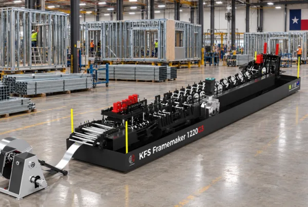
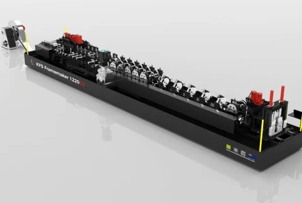
Every non-load-bearing steel stud wall that runs from floor to floor has the same problem at its head. The structure above it moves, and the wall must not stop it. Slotted deflection track, also called slip track in North America and a slotted deflection head in the UK, solves that problem with a row of vertical slots that let the floor or roof above deflect while the studs stay put. It is one of the most common pieces of light-gauge steel framing on any commercial project, and one of the most tedious to make.
This article explains why slotted track is used, how much movement it has to absorb in different kinds of buildings around the world, which track and slot sizes are standard, and what the codes require for screw edge distance. It also shows the three ways Scottsdale's steel framing roll formers produce slotted track, from computer-placed slots that appear only where studs land to a six-slot punch that makes continuously slotted track 3.7 times faster.
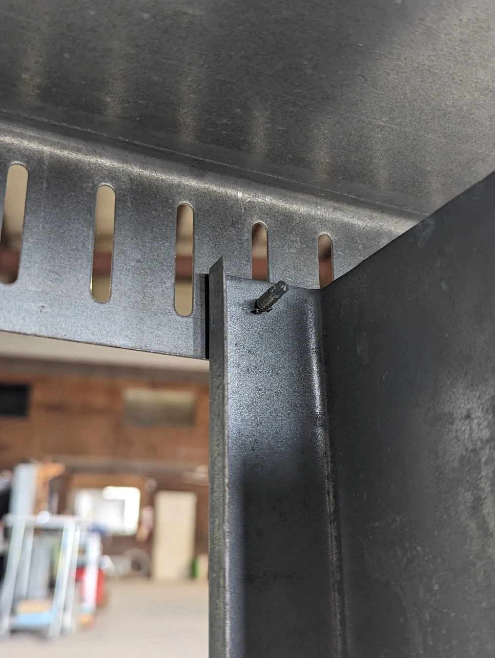
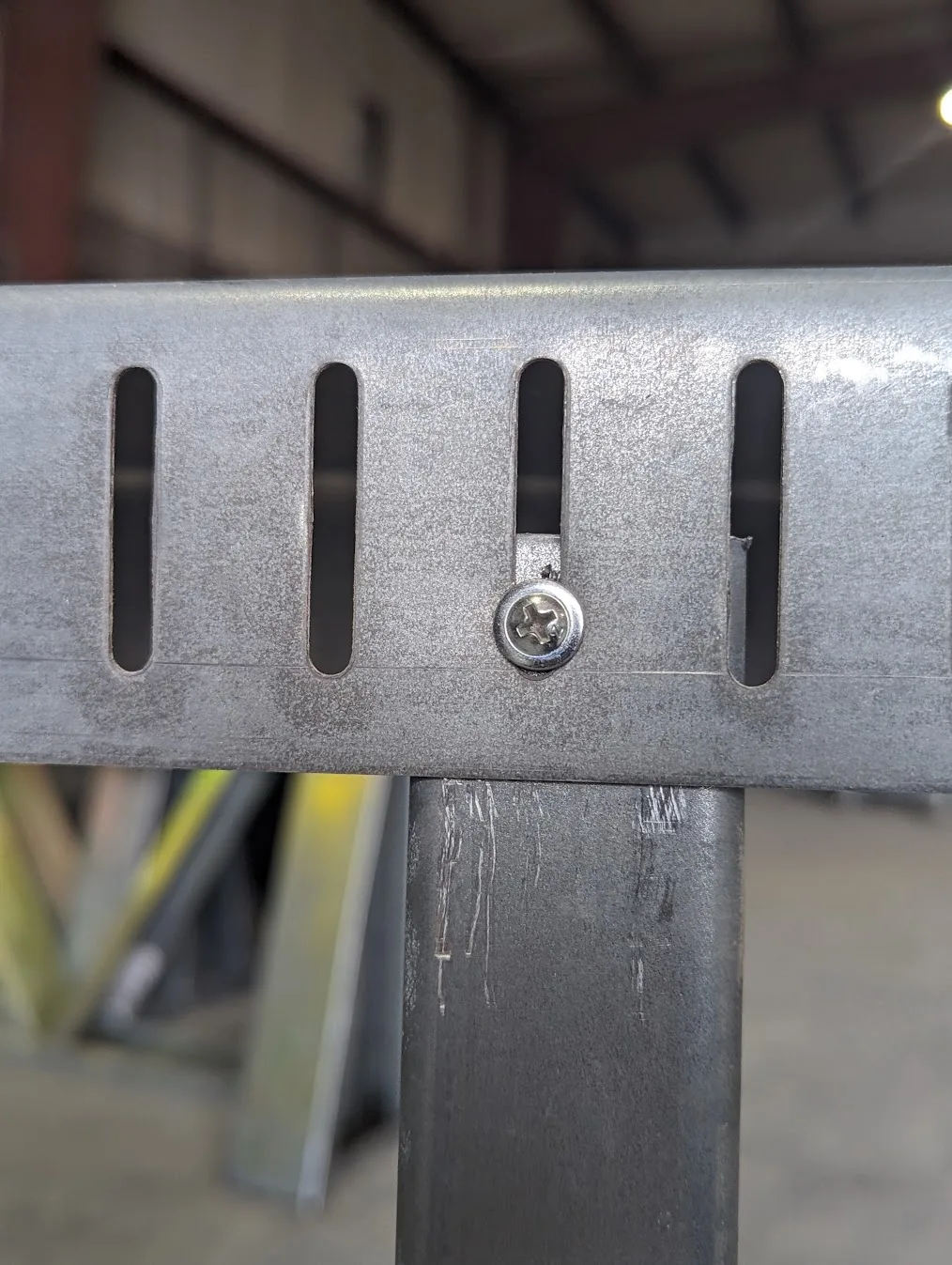
Slotted track from the KFS Framemaker 1220G3
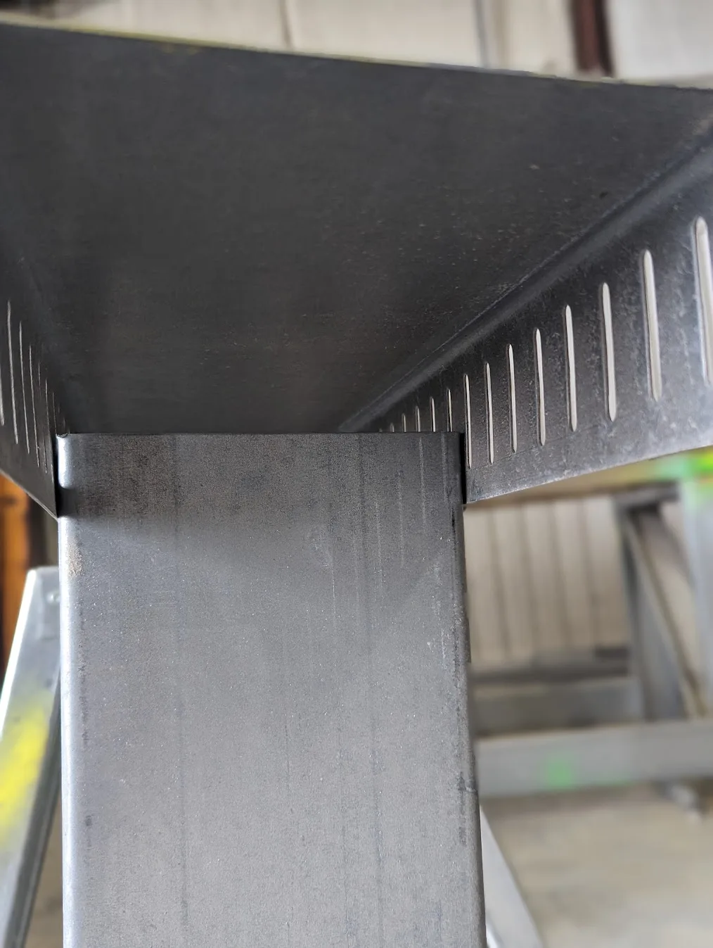
The three photos below show slotted deflection track and studs roll formed on the KFS Framemaker 1220G3, Scottsdale's newest multi-profile steel framing roll former.
Why slotted deflection track is used
A curtain wall, an exterior infill wall or an interior partition built with cold-formed steel studs is designed to carry wind, seismic and interior lateral loads, but not the weight of the building. The floor slab or roof above it, however, deflects under live load, snow, creep and shrinkage, and it keeps deflecting for years after the wall is finished. If the studs were screwed tight to the track at the top of the wall, that movement would push down on the studs, turning a non-load-bearing wall into an accidental load-bearing one. The studs could buckle, the gypsum board could crack, and the wall could even prop up the slab and redistribute loads the structural engineer never intended.
Slotted track breaks that path. The track is fastened to the structure above, and the studs are screwed to the track through vertical slots. The screws resist the out-of-plane lateral load and keep each stud in line, while the slots let the track move up and down past the screws. The studs are cut short so that a deliberate gap remains between the stud ends and the track web.
Scottsdale's own multi-punch deflection track announcement summarizes the main drivers. Movement between the primary structure and the steel framing system (SFS) comes from wind, seismic activity and snow load, and in heavy-snow regions codes may require a deflection track to absorb seasonal changes in roof loading. For exterior walls where studs run slab to slab, the slotted track lets the floor or roof above deflect without passing axial load into the studs.
In practice, slotted track does four jobs at once:
- It isolates the non-load-bearing wall from vertical movement of the structure above.
- It transfers lateral load from the studs into the slab or deck through the screws.
- It keeps each stud plumb and correctly spaced, which a deep-leg track without screws does less reliably.
- It gives the installer a positive connection that inspectors can see and verify.
Where Scottsdale machines produce slotted track
Slotted track is not a specialty product reserved for a single machine. Scottsdale builds it into most of its current steel framing machines, from dedicated steel stud roll formers to multi-profile lines, so a fabricator can produce slotted track alongside studs, joists and trusses from the same coil.
Slotted track capability is a standard feature on these machines:
| Machine family | Models | Typical market |
|---|---|---|
| Scotpanel G3 | 7090G3, 5090G3, 5140G3, 7140G3, 8140G3, and other G3 models | Panelized housing, offsite construction and walls with exterior continuous insulation |
| KFS Framemaker | 1420G2, 1622G2 and 1220G3 | Structural and panelized framing, commercial and mid-rise work |
| KFD Framemaker | 2025G2 | Non-load-bearing interior and curtain wall framing for wall and ceiling contractors |
Slotting can also be added as an extra feature to some other Scottsdale models. If you run an earlier-generation machine, contact Scottsdale to ask whether your machine can take the toolkit.
Three ways to produce slotted track
Not every project needs the same kind of slotted track. A panelizer building finished wall panels for a known floor plan needs something different from a supplier selling slotted track by the bundle. Scottsdale machines offer three production approaches.
1. Computer-placed slots only where studs land
The fastest slot to punch is the one you don't punch. Conventional slotted track carries a slot roughly every inch along both flanges, because the supplier doesn't know where the studs will go. A machine that knows the wall layout can punch a slot only at each stud location.
All Scotpanel G3, KFS Framemaker G2 and KFD Framemaker G2 machines can place deflection slots this way, driven by the ScotSteel software suite from the 3D framing model. On the KFS Framemaker 1220G3, this is the method used in panelizer mode, where studs and track are formed from the same C-section and coil and assembled into panels as they come off the machine.
The savings are large. A 10-foot (3 m) track slotted at 1-inch (25 mm) pitch carries 120 slots per flange. With studs at 16 inches (406 mm) on center, the same track needs only eight, which is about 93% fewer punch strokes. At 24-inch (610 mm) spacing the reduction is even greater. Fewer strokes mean faster production and less wear on the punch tooling.
There are two further benefits that are easy to overlook. First, the track flange keeps its full, unpunched section between studs, so it is stiffer and stronger as it spans between studs carrying lateral load. Second, the slot pattern itself becomes an assembly guide, because every slot marks exactly where a stud belongs.
Most importantly, computer-placed slots make it possible to panelize non-load-bearing walls. A prefabricated partition or curtain wall panel can leave the factory with its slotted head track already fitted and its studs screwed into the slots, ready to accommodate deflection once it is installed. This is a capability that sets the KFS Framemaker 1220G3 apart, and it extends the schedule and labor benefits of prefabrication to the non-load-bearing walls that make up most of a commercial fit-out.
2. Continuous slots at close intervals
Some situations call for traditional, continuously slotted track. Suppliers selling stud and track in bulk don't know where their customers' studs will go, and panelizers sometimes need room for in-field adjustment when a stud has to shift around a duct, a pipe or an as-built condition.
The same machines that place slots by computer can also punch single slots at close, regular intervals along the whole track. On the KFS Framemaker 1220G3, this is the approach used in hybrid mode, where lipped C-studs and unlipped U-track are produced in separate batches for stud-and-track supply, with panelization still available. Fabricators can switch between computer-placed and continuous slotting from one job to the next without changing the machine.
3. The six-slot multi-punch tool for high-volume suppliers
When continuously slotted track is the main product, punching one slot per stroke becomes the bottleneck. Scottsdale developed an in-line multi-punch deflection track tool with its launch customer, US Frame Factory, to remove that bottleneck. The tool punches six slots in a single stroke, which makes production of continuously slotted track 3.7 times faster, as Scottsdale showed in its LinkedIn announcement. At 1-inch pitch, a 10-foot track flange needs 20 strokes instead of 120.
The six-slot tool is optional tooling for all KFS Framemaker and KFD Framemaker models. It is the right choice for stud-and-track suppliers, distributors and contractors who sell slotted track by the bundle.
Choosing the right approach
| Approach | Slots per 10 ft (3 m) flange | Best for | Machines |
|---|---|---|---|
| Computer-placed slots at studs | About 5 to 8, one per stud | Panelized non-load-bearing walls with a fixed layout | All Scotpanel G3, KFS G2, KFD G2, and KFS 1220G3 in panelizer mode |
| Single slots at close intervals | About 120 | Bulk supply, or panels that need field adjustment | The same machines, and KFS 1220G3 in hybrid mode |
| Six-slot multi-punch tool | About 120, in 20 strokes | High-volume slotted track supply | Optional on all KFS and KFD Framemaker models |
The slotting tools in the Scottsdale punch catalogue
Scottsdale's KFD and KFS Framemaker In-Line Punch Tool Catalogue lists every in-line punch available for these machines. It separates tools that punch the flat coil before forming (flat state) from tools that punch the finished section (finished state). These are the flange slotting tools:
| Tool code | Description | State | Catalogue page |
|---|---|---|---|
| FLF-4 | Slip track slot (flange) | Flat | Page IV–38 |
| FLF-3 | Flange slot, 6X (the six-slot multi-punch tool) | Flat | Page IV–37 |
| FIF-1 | 0.13 × 0.63 in. slot (flange) | Finished | Page II–2 |
| FIF-2 | 0.13 × 1.25 in. slot (flange) | Finished | Page II–3 |
| FIF-4 | 0.188 × 0.75 in. slot (flange) | Finished | Page II–5 |
The catalogue also lists several web slots, such as 0.75 × 4.00 in. and 1.50 × 3.00 in., but these are service openings for pipes and wiring rather than deflection slots.
The standard deflection slot depends on the machine:
| Machine | Standard deflection slot |
|---|---|
| KFD Framemaker 2025G2 | 0.22 × 1.50 in. (5.6 × 38 mm) |
| KFS Framemaker 1622G2 and 1420G2 | 0.22 × 1.50 in. (5.6 × 38 mm) |
| KFS Framemaker 1220G3 | 0.25 × 1.50 in. (6 × 38 mm) |
The 1220G3 slot is listed under Fabrication and Tooling in the KFS Framemaker 1220G3 Technical Specification. Both standard sizes share the 1½-inch slot length most commonly used in North American slotted track, and the 0.22-inch width matches widely specified manufactured slip track. Other slot sizes are available as optional tooling, as listed in the SM3 punch tool catalogue above.
How much movement does the head of the wall need?
The movement a slotted track must absorb depends on the structure above it, and every country frames that requirement a little differently. Most codes limit the deflection that occurs after partitions are installed, because that is the movement the wall actually sees. The figures below are typical values for planning purposes. The structural engineer of record (EOR) sets the actual movement for each project.
Reinforced concrete frames and flat slabs
In the United States, ACI 318-19 Table 24.2.2 limits the deflection that occurs after nonstructural elements are attached to span/480 when those elements are likely to be damaged, and span/240 when they are not. In Europe, Eurocode 2 suggests limiting post-construction deflection to span/500 where partitions are attached to the member, and the older British Standard BS 8110 used span/500 or 20 mm, whichever is less, for brittle finishes, according to a review of code limits in The Structural Engineer. For an 8 m (26 ft) span, span/480 is about 17 mm (0.66 in.) and span/500 is 16 mm.
In British practice the slotted head track is usually called a deflection head, and the movement it must accommodate is specified in millimetres. UK SFS specialists typically detail concrete-frame deflection heads for 10 to 15 mm of movement, according to BAS Frames. In Australia, AS 3600 limits total deflection to span/250, and Tonkin notes that even a span/1000 limit will not stop masonry partitions from cracking, which is why it recommends articulating partitions so they can move. A slotted head track is exactly that kind of articulation.
Post-tensioned flat plates
Post-tensioned (PT) slabs are thin and economical, but their deflections are harder to predict, especially at slab edges and cantilevers. In a Post-Tensioning Institute paper, engineer Douglas Sarkkinen recommends targeting long-term plus live-load deflections of about 3/8 in. (10 mm) for condominiums, 1/2 in. (13 mm) for offices and 3/4 in. (19 mm) for parking garages in typical 30-foot bays. The same paper notes that slab edges and cantilevers are very sensitive to tendon placement and that construction tolerances of ±3/4 in. apply on top of deflection. A standard slotted track with ±3/4 in. of travel covers typical interior PT bays, but walls under slab edges and cantilevers often need a deeper slot or a purpose-made PT deflection connector.
Structural steel and composite floors
Steel-framed buildings with composite deck floors usually move more than concrete frames. UK practice allows 15 to 25 mm for composite slabs and 30 mm or more for long-span steel frames, which need a bespoke calculation, according to BAS Frames. In North America, a span/360 live-load limit has long been used for floors over non-load-bearing partitions. For a 9 m (30 ft) beam, span/360 is 25 mm (1 in.), which already exceeds the ±3/4 in. of a standard slotted track. On long spans, check the actual post-installation deflection before choosing a standard slot.
Metal buildings
Pre-engineered metal buildings are the most flexible structures that steel stud walls attach to. A standard metal building with metal roof and wall panels typically has a lateral drift limit of eave height divided by 60 under a 10-year wind, according to Nucor Building Systems. For a 14-foot (4.3 m) eave, that allows 2.8 in. (71 mm) of sidesway. Roof purlins and rafters also deflect under snow. A partition or liner wall built tight to that structure needs far more than a standard slot, so designers usually stop interior walls short of the roof and brace them independently, or use long-slot clips that allow 2 to 3 in. of travel.
Lateral drift and seismic movement
Slotted track handles vertical movement. It does not handle in-plane racking from lateral drift. The Steel Network recommends providing at least ½ in. (13 mm) of in-plane movement at the head of exterior walls in seismic areas, in its guide to deep-leg track design. AISC's Design Guide 3 overview cites common interstory drift limits of story height divided by 600 to 400, and an absolute limit of 3/8 in. (10 mm) where nonstructural elements are not detailed for more. Where drift governs, use two-way (vertical and horizontal) deflection track or drift clips.
Summary of typical head-of-wall movement
| Structure | Typical movement to accommodate | Is a standard 1½ in. (38 mm) slot enough? |
|---|---|---|
| RC flat slab or frame, moderate spans | 10 to 15 mm (3/8 to 5/8 in.) | Yes, with margin |
| PT flat plate, interior bays | 10 to 19 mm (3/8 to 3/4 in.) | Usually, if the screw is placed correctly |
| PT slab edges and cantilevers | Project-specific, often more than 19 mm | Often not, so use deeper slots or PT connectors |
| Composite steel floor | 15 to 25 mm (5/8 to 1 in.) | Borderline, so check the actual value |
| Long-span steel frame | 30 mm (1¼ in.) or more | No, so use long-slot clips or deep-leg track |
| Metal building roof and frame | 50 mm (2 in.) or more | No, so isolate the wall or use long-slot clips |
| Heavy snow regions | Seasonal roof movement set by the EOR | Check against the roof deflection |
Standard track and slot sizes
North American steel stud and track sizes follow AISI S220, the standard for nonstructural cold-formed steel framing. Its standard track web depths are 1-5/8, 2-1/2, 3-5/8, 4 and 6 inches, with standard flange widths of 1-1/4 and 1-1/2 inches. Deflection track uses longer flanges, commonly called legs, so the studs remain engaged as the gap opens and closes. A typical manufactured slotted track, such as ClarkDietrich's MaxTrak SLT, has 2½-inch legs with slots 1½ inches long and 0.22 inches wide at 1-inch centers, providing 1½ inches of total travel (±3/4 in.).
Outside North America, the same principles apply to metric sections. UK and European drywall and SFS systems use galvanised metric C-studs and U-tracks, with head tracks designed for the 10 to 25 mm deflections common in UK practice, and Australian and New Zealand systems follow their own metric sizes. Scottsdale's Scotpanel machines form 63, 70, 76, 90 and 140 mm C-sections, and the KFS Framemaker 1220G3 forms any C-section from 89 to 305 mm (3.50 to 12.00 in.) deep with flanges up to 89 mm (3.50 in.), so track legs can be sized to the slot rather than the other way around.
| Wall type | Typical track | Typical slot | Typical travel |
|---|---|---|---|
| Interior partition, non-structural | 20 to 25 gauge, 2 to 2½ in. legs | About ¼ × 1½ in. (6 × 38 mm) | ±3/4 in. (±19 mm) |
| Exterior curtain wall, structural | 33 to 68 mil, 2½ to 3 in. legs | About ¼ × 1½ in. (6 × 38 mm) | ±3/4 in. (±19 mm) |
| Long-span or metal building heads | Long-slot clips or deep-leg track | 3 in. (76 mm) slots | Up to 3 in. (76 mm) total |
Code edge distance for screws in slotted track
Screws in slotted track still have to meet the minimum edge distance and spacing rules in the steel standards. Under AISI S220 Section B3.1.2.1, which follows AISI S100, the minimum edge and end distance for steel-to-steel screws is 1.5 times the nominal screw diameter. Screws should be spaced at least 3 diameters apart to be considered fully effective, and screws spaced between 2 and 3 diameters are 80% effective.
For the screws used most often in slotted track, these rules work out as follows:
| Screw | Nominal diameter | Minimum edge distance (1.5d) | Full-strength spacing (3d) |
|---|---|---|---|
| #8 | 0.164 in. (4.2 mm) | 0.246 in. (6.2 mm) | 0.49 in. (12.5 mm) |
| #10 | 0.190 in. (4.8 mm) | 0.285 in. (7.2 mm) | 0.57 in. (14.5 mm) |
The edge that matters most in slotted track is the free edge of the track flange below the slot. When the structure above rises to its highest point, the screw ends up at the bottom end of the slot, and its center must still be at least 1.5 diameters from the edge of the flange. Because the screw's center sits half a diameter inside the end of the slot, this works out to a simple rule: leave at least one screw diameter of solid steel between the bottom of the slot and the edge of the track leg. The same 1.5d rule applies to the end distance in the stud, measured from the screw to the cut end of the stud.
How thick should the track be? The SSMA method
A deflection track does more than hold a slot. Each stud pushes its share of the wall's lateral load into the track leg, and the leg has to resist that push as a short cantilever plate. If the leg is too thin, it bends outward, the stud loses its support, and the wall can deflect far more than intended. The Steel Stud Manufacturers Association (SSMA) published a design method for this in its technical note Single Deflection Track Selection, based on the U.S. Army Corps of Engineers' effective-width method in ETL 1110-3-411.
The method treats the stud's top reaction P as a point load acting at a distance e from the track web, spread over an effective width beff of the track leg. The required design thickness is:
t = √( 7.5 · P · e / ( Fy · beff ) )
In this equation, P is the stud's top reaction in pounds, which for a simply supported stud is the lateral pressure times the stud spacing times the wall height divided by two. Fy is the track's minimum yield stress in psi, and e is taken as 1.5 times the design gap. SSMA's design curves assume a 1¼-inch stud flange, and the effective width spreads from the stud flange at 60° on each side:
beff = bstud + 2 (e + 1.25) tan 60°
The equations in SSMA's scanned note are difficult to read, so we confirmed this form by reproducing SSMA's own worked example. For a 5 psf interior load, studs at 24 inches on center, a ½-inch gap and 33 ksi steel, the method gives a maximum wall height of 19.52 feet for 18-gauge (43-mil) track, exactly matching SSMA's published result.
SSMA adds four conditions that every fabricator should know:
- Leg depth. The track leg should be at least the design gap plus 1 inch for one-story buildings, and twice the design gap plus 1 inch for multi-storey (multi-story) applications.
- Ductility. Deflection track steel should have a tensile-to-yield ratio of at least 1.08 and an elongation of at least 10% in a 2-inch gauge length. Both values appear on a mill test report, and Scottsdale's free ScotCalc Coil Analyzer checks them against AISI S100 before a coil reaches the machine.
- Wind and seismic reduction. The reaction may be multiplied by 0.75 for wind or earthquake loads only where the local code allows it.
- Delivered thickness. The minimum delivered thickness may be 95% of the design thickness.
Leg depth also tells you which machine can make the track. The KFD Framemaker 2025G2 forms track flanges up to 2.0 inches, which suits gaps up to 1 inch in one-story buildings or ½ inch in multi-story buildings. The KFS Framemaker 1220G3 forms track flanges up to 3.50 inches, which covers gaps up to 2½ inches in one-story buildings and 1¼ inches in multi-story buildings.
Reference table: maximum wall height by track thickness
The table below applies the SSMA method to a typical interior partition with a 5 psf lateral load and 33 ksi track, with no wind or seismic reduction. Each value is the tallest wall, in feet, that the track thickness can support. Values above 30 feet are shown as 30+ because they exceed typical partition heights.
| Track thickness | ½ in. gap, studs at 16 in. | ½ in. gap, studs at 24 in. | ¾ in. gap, studs at 16 in. | ¾ in. gap, studs at 24 in. |
|---|---|---|---|---|
| 20 ga (33 mil, 0.0346 in.) | 17.2 ft | 11.5 ft | 13.3 ft | 8.9 ft |
| 18 ga (43 mil, 0.0451 in.) | 29.3 ft | 19.5 ft | 22.6 ft | 15.1 ft |
| 16 ga (54 mil, 0.0566 in.) | 30+ ft | 30+ ft | 30+ ft | 23.7 ft |
| 14 ga (68 mil, 0.0713 in.) | 30+ ft | 30+ ft | 30+ ft | 30+ ft |
Two patterns stand out. A larger gap costs more capacity than most people expect, because it pushes the load farther from the web: going from a ½-inch to a ¾-inch gap cuts the allowable height by about 23%. Wider stud spacing costs even more, because each stud carries more load into a single point on the track. Exterior walls with 15 to 30 psf wind loads need heavier track or closer studs, which is where the calculator below helps.
Track within a track
SSMA's companion note, Track Within a Track Deflection Assembly, applies the same equation to a nested assembly. The studs are screwed to an inner track, which slides inside an outer deflection track fastened to the structure, and the two tracks are not attached to each other. Because the inner track spreads the stud reactions along the outer leg, the load is treated per foot of wall rather than per stud. SSMA's worked example, a 13-foot-6-inch wall at 15 psf with a ½-inch gap and 33 ksi steel, calls for 18-gauge track with a maximum height of 19.0 feet, and our calculation reproduces it. The inner track legs follow the same gap-plus-1-inch and twice-the-gap-plus-1-inch rules, so the stud screws stay clear of the movement.
Track within a track also suits panelization. A non-load-bearing panel can leave the factory with its own inner top track fully screwed to the studs, and the installer fixes only the outer track to the slab on site. Both tracks come off the same roll former.
What this means for slotted track
SSMA's method was written for unscrewed deep-leg track, where the stud bears on the leg near its tip. In slotted track, the screw carries the stud reaction into the leg at the slot. For a conservative check, take e as the distance from the track web to the screw at its lowest position in the slot, rather than 1.5 times the gap. Because the screw usually sits lower in the leg than the bearing point of an unscrewed stud, this check often calls for heavier track than the deep-leg method. Final track selection belongs to the EOR or the track manufacturer's tested values.
Deflection track thickness calculator
The calculator below runs the SSMA method for single deflection track, track within a track, and slotted track with a screw at a set distance from the web. Enter the lateral load, stud spacing, wall height and gap, and it returns the required design thickness, the lightest standard gauge that works, the maximum wall height for each gauge, and the leg depth SSMA recommends.
SSMA effective-width method for single deflection track, slotted track and track within a track.
| Gauge | Min. thickness | Design thickness | Max. wall height | At your height |
|---|
Method: SSMA, Single Deflection Track Selection and Track Within a Track Deflection Assembly (2000), after USACE ETL 1110-3-411. t = √(7.5·P·e / (Fy·beff)); e = 1.5 × gap; beff = 1.25 + 2(e + 1.25)·tan 60° in inches, for a 1¼-in. (32 mm) stud flange, or 12 in. per foot of wall for track within a track. For slotted track, e is the distance from the web to the screw at its farthest point, a conservative check. Track steel should have Fu/Fy ≥ 1.08 and at least 10% elongation, and delivered thickness may be 95% of design thickness. This calculator is a preliminary design aid. Final track selection is the responsibility of the engineer of record or the track manufacturer's tested values. © Scottsdale Construction Systems.
Practical guidelines for designing and producing slotted track
These guidelines come from the geometry of the slot and the experience of fabricators who produce slotted track every day. They are not a substitute for the EOR's design, but they catch the most common mistakes.
Separate tolerance from movement. A head-of-wall detail absorbs two different things: the construction tolerance in the slab-to-slab height, and the deflection that happens in service. Concrete floors alone can vary by ±3/4 in. in elevation under ACI 117. If the slot has to absorb both, it runs out of travel. Cut studs to the as-built height, or use telescoping studs from a FrameExtend24, so the slot is reserved for movement.
Usable travel is shorter than the slot. A screw has a diameter, so it can only travel the slot length minus the screw diameter. A 1.50-inch slot with a #8 screw gives about 1.34 inches (34 mm) of real travel, not 1.50 inches. Design to the usable figure.
Make the gap and the slot agree. The travel available downward is the smaller of two things: the room left in the slot above the screw and the gap between the stud end and the track web. If the stud gap is ½ inch but the slot leaves ¾ inch above the screw, the stud hits the track web first and starts carrying load. Set the screw position and the stud gap together.
Place the screw for the expected direction of movement. Center the screw in the slot when movement can go both ways, for example where live load comes and goes. Bias the screw toward the bottom of the slot, as in the third photo above, when the engineer expects mostly downward movement after installation, such as long-term creep of a concrete slab. Mark the screw line on the track or the panel drawing so installers get it right.
Do not over-drive the screws. Use low-profile wafer or pan-head screws and snug them without clamping the track, so it can slide. A screw driven tight enough to lock the track defeats the slot.
Remember multi-storey (multi-story) walls. Where a wall spans between two floors that can both deflect, the head must absorb the relative movement between them. The Steel Stud Manufacturers Association recommends a track leg of twice the design gap plus 1 inch for multi-story applications, compared with the gap plus 1 inch for one-story buildings, in its single deflection track selection guide.
Lock panels for shipping, then release them. A prefabricated panel with studs screwed into slotted head track can rack or telescope in transit. Hold the studs at their design position with temporary fasteners or bracing, and remove the temporary fasteners after installation so the slots are free to work.
Rated walls need a rated joint. In fire-rated walls, the head-of-wall joint must be a tested system, such as one listed under UL 2079 or ASTM E1966 in North America or tested to EN 1366-4 in Europe. The slot and gap in the track must match the tested assembly.
Alternatives to slotted track
Slotted track is the most common head-of-wall connection, but it is not the only one. The Steel Network's design guide lists four basic options: slotted clip angles, slotted track, single deep-leg track with no screws into the studs, and double track.
| Solution | How it works | Strengths | Limitations |
|---|---|---|---|
| Slotted track | Studs screw through vertical slots in the track legs | Positive, visible connection that keeps studs aligned | Travel is limited by slot length, usually ±3/4 in. |
| Deep-leg track | Studs sit in a long-legged track without screws | Simple and fast to install | Needs bridging near the top to stop stud rotation, and the track must be designed for bending |
| Double track (track within a track) | An inner track carrying the studs slides inside an outer track fixed to the slab | Large travel, and the studs are screwed to their own track | More steel and more pieces |
| Deflection clips | Slotted clip angles connect each stud to the structure | Large travel and high capacity | One clip per stud, which adds material and labor cost |
Deflection clips from The Steel Network (TSN) are the best-known alternative. The VertiClip SLD with 3-inch slots connects interior studs to the deck through a slotted clip and allows up to 3 inches of total vertical movement. TSN's step bushings keep the connection from binding, and TSN states the clip is designed for horizontal loads and should not be used in axial load-bearing walls. TSN's VertiTrack combines track with pre-installed clips, and its DriftTrak line adds horizontal drift capacity, including a version for post-tensioned slabs. Clips are the right answer for long spans, metal buildings and PT slab edges, where a 1½-inch slot runs out of travel. For the large majority of walls under concrete and moderate-span steel floors, slotted track produced in-line on a roll former remains the most economical solution.
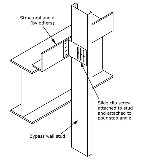
A slide clip connects a bypass wall stud to a structural angle at a steel beam. The screws through the clip's vertical slots let the floor move without passing axial load into the stud. Source: Steel Stud Manufacturers Association (SSMA), typical details, page 34.
The clip in the SSMA detail above does the same job as slotted track, but it moves the slot from the track into a separate clip at each stud. That makes it the natural choice for bypass framing, where the studs run continuously past the edge of the floor and there is no head of wall at all. SSMA notes that this kind of clip lets the floor or roof move vertically without imparting axial load to the wall framing, and that it absorbs variation in the slab edge so the wall stays in line.
SSMA typical details worth bookmarking
SSMA's typical details set includes several head-of-wall and movement details that pair naturally with slotted track. The page numbers below are PDF page numbers, and each link opens the PDF at that page.
| PDF page | SSMA detail | Why it matters |
|---|---|---|
| 29 | Deflection track assembly: single track with cold-rolled channel | A cold-rolled channel through the stud punchouts braces the studs near the top, so the studs are not screwed to the track. SSMA notes it allows both vertical and horizontal movement of the structure above. The punchouts must line up, which is easy when the roll former punches every service hole at the same distance from the stud end. |
| 30 | Deflection track assembly: double deflection track | The track-within-a-track assembly described above. SSMA notes that it ties the studs together laterally without relying on the cladding for support parallel to the wall. |
| 33 | Bridging: cold-rolled channel with angle clip | The bridging that keeps studs from rotating below a deflection head. SSMA calls for a clip angle about 80% of the stud depth and at least 43 mil thick. |
| 34 | Bridging: full-height curtain wall deflection clip | The slide clip shown above, for bypass curtain walls that run past the floor edge. |
| 35–37 | Spandrel curtain wall details at steel beams | Stickers, drops and diagonal braces (at 45° or less) that support spandrel framing from a beam. A deflection connection is still needed wherever the framing meets a floor that moves. |
| 44–45 | Non-load-bearing interior walls with diagonal kickers | Partitions that stop above or at the ceiling and are braced back to the structure with kickers. These avoid a full-height deflection head altogether, which is often the best answer in metal buildings with large roof movement. |
| 14–16 and 26–28 | Non-load-bearing window and door openings with single track headers | Openings in a partition under a deflection head need the same care. The jamb studs must stop short of the structure with the same gap as the field studs, or they will carry the floor load the slotted track was meant to avoid. |
A complete three-machine set for wall and ceiling panelizers
Wall and ceiling contractors need more than studs and track. Scottsdale offers a three-machine set built specifically for drywall, curtain wall and ceiling framing:
- KFD Framemaker 2025G2. This machine forms non-load-bearing studs and track with webs from 1-5/8 to 6 inches and includes a track slotting toolkit as standard. It is optimized for non-structural interior and exterior framing and is one of the most popular machines among wall and ceiling contractors.
- FrameExtend24 (FE24). The FE24 rolls a smaller C-section that slides inside a standard stud to make telescoping, extendable studs and boxed sections. Pre-assembled telescoping panels can extend to the as-built floor-to-floor height, and they can travel through elevators and tight spaces before being extended. Paired with the KFD's deflection slots, it reduces dimensional uncertainty, rework and on-site cutting.
- K35C. The K35C is a power pack with interchangeable roll forming cassettes for furring channels, resilient furring channels, corner bead struts, U-struts and other accessory sections for interior and exterior finishes. Scottsdale's cassette exchange video shows how quickly one profile changes to another.
Together the KFD, FE24 and K35C let a wall and ceiling contractor produce studs, slotted track, telescoping studs, furring and accessories in house. Combined with ScotSteel, the set can deliver finished non-load-bearing panels that arrive cut to the building and ready to accommodate its movement.
Built with the industry, for the industry
Scottsdale is a member of the Association of the Wall and Ceiling Industry (AWCI) and the Steel Framing Industry Association (SFIA). Those memberships keep us close to the contractors and producers who build non-load-bearing walls every day, and to the problems they ask us to solve. The multi-punch deflection track tool came out of exactly that kind of collaboration with a fabricator, and computer-placed slots for panelized non-load-bearing walls respond to the industry's shift toward prefabrication. Our article on the 2026 Wall and Ceiling Industry Trends Report explains why that shift is accelerating, and our guide to reaching R-21 with 3½-inch steel studs shows how the same machines serve high-performance exterior walls.
The bottom line
Slotted deflection track keeps non-load-bearing steel stud walls from becoming load-bearing by accident. A standard 1½-inch slot covers most concrete-frame and moderate-span steel buildings, while long spans, metal buildings and PT slab edges call for longer slots, deep-leg track or deflection clips. Getting the detail right depends on separating construction tolerance from structural movement, matching the stud gap to the slot, and keeping the screws within code edge distances.
On the production side, Scottsdale steel framing roll formers give fabricators a choice. Computer-placed slots cut punch strokes by more than 90% and make panelized non-load-bearing walls possible. Continuous slots serve bulk supply and field adjustment. The six-slot multi-punch tool makes continuously slotted track 3.7 times faster for high-volume suppliers. To find the right roll forming machine for your wall and ceiling work, contact Scottsdale, explore the free ScotCalc engineering tools, or read our customer stories.
Sources
- Scottsdale: A new multi-punch deflection track tool
- Scottsdale on LinkedIn: six-slot deflection track punch tooling
- Scottsdale KFD and KFS Framemaker In-Line Punch Tool Catalogue, version 2025.2
- Scottsdale KFS Framemaker 1220G3 Technical Specification, version 2026.2
- Scottsdale: Feature Rich KFS 1220G3, the complete roll forming modes
- Scottsdale Scotpanel machines
- Scottsdale KFS Framemaker roll formers
- Scottsdale KFD Framemaker roll formers
- Scottsdale KSE machines: K35C and FrameExtend24
- Scottsdale: FrameExtend24
- AISI S220-20, North American Standard for Cold-Formed Steel Framing: Nonstructural Members
- SSMA: Single deflection track selection
- SSMA: Track within a track deflection assembly
- SSMA: Typical details
- Scottsdale: ScotCalc Coil Analyzer
- The Steel Network: Design of single deep-leg track to accommodate vertical deflection
- The Steel Network: VertiClip SLD with 3-inch slots
- ClarkDietrich MaxTrak SLT submittal sheet
- ACI 318-19 Table 24.2.2 deflection limits (ideCAD summary)
- Sarkkinen, PT Slab Deflections: What Is Acceptable? (Post-Tensioning Institute)
- Camilleri, Deflection and preliminary vibration effects on structural elements, The Structural Engineer
- Tonkin: The deflection of reinforced concrete
- BAS Frames: SFS deflection heads explained
- AISC: Design Guide 3, serviceability considerations
- Nucor Building Systems: metal building drift engineering tips